MUNAS RAPI 2010

Sabtu, 29 Januari 2011
The HO Collinear, a Horizontal Omni
 Figure 1
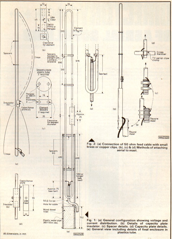
This paper describes a high gain, multi-element horizontal omni with a single 50 ohm feedpoint with instructions for building a 4 element array for 2 meters.
There are several ways to make a horizontal omni [1,2,3,4,5]. One popular type is the HO which is a half wave dipole folded into a square or a circle [6,7]. The impedance of this antenna is not 50 ohms and requires a matching section. If more gain is desired, then two or more elements can be stacked collinearly, with each element fed separately through power dividers.
A simpler way to combine elements is to connect the loops together by adding vertical extensions to the ends of each loop. The lengths of the loops and vertical wires are adjusted for maximum horizontal gain consistent with a 50 ohm feedpoint in the center of the bottom loop using an antenna modeling program. Since I decided to use 3/8 inch diameter soft copper tubing for the horizontal loops and # 18 wire for the vertical wires, I used mininec because nec cannot be used for antennas made of two wires of very different diameter [8,9]. It is possible to build this antenna with only one diameter wire, in which case nec can be used [10].
A test antenna was made for 144.5 MHz consisting of four horizontal loops made of 3/8  inch diameter soft copper tubing and two #18 (0.040 inch diameter) vertical wires. A loop drawing is shown in Figure 2. For the top and bottom loops, L = 31 7/16 and S = 1 5/8. For the middle loops, L = 28 5/16 and S = 1½. Cut the copper tubing to the lengths shown and bend them to approximate a circle with a gap
  as shown. All dimensions are in inches.
inch diameter soft copper tubing and two #18 (0.040 inch diameter) vertical wires. A loop drawing is shown in Figure 2. For the top and bottom loops, L = 31 7/16 and S = 1 5/8. For the middle loops, L = 28 5/16 and S = 1½. Cut the copper tubing to the lengths shown and bend them to approximate a circle with a gap Then support the elements in some way. I used a piece of ¾ inch schedule 40 pvc pipe. The spacing between the elements (and the length of the vertical wires) should be 20 7/8 inches. Figure 3 shows how the vertical wires and the loops are connected together. This figure is drawn from the point of view off axis from the top of the antenna. The antenna is fed in the center of the bottom loop. As with other off center fed antennas, the feed point is not balanced, so a current balun is required. See my Quadix page [11] for balun references.
Figure 1 shows the assembled antenna on the roof. No patterns were taken, but the SWR (Figure 4) agreed with the simulated SWR (except for a 1% frequency offset error) which gives confidence that the antenna is working properly. The simulated gain is 3.27+/-1.22 dBi.
Figure 
 4
4
4Figure 3
Adding more elements will improve the gain. If you decide to change the design using different diameters, more elements, or a different frequency, you should resimulate using mininec. Mininec typically has frequency offset errors, so the final design may have to be tweaked a bit. I increased the vertical wire lengths from 20 to 20 7/8 inches from my original simulation (keeping the loop lengths the same). The frequency can also be adjusted by varying the gap at the end of the loops. Closing the gap lowers the resonant frequency (and also the impedance). Increasing the gap increases the gain variation (i.e., makes it less omni). If you decide to use the same diameter for the vertical and horizontal elements, then nec can be used, but it may not be possible to get to 50 ohms.
One further comment: The spacing between the loops is smaller than is usually used in collinear arrays. This is because the electrical length between the centers of each loop is a half wavelength. The radiation from the loops is kept in phase by reversing the wire direction between adjacent loops (See Figure 3).
Antena Quadix 10.2Db
The Quadix

The Quadix is a circularly polarized parasitic array, a hybrid between a helix and a quad (or loop yagi). As is the case with other yagi type parasitic arrays, it has a reflector and as many directors as desired. A two turn helix is used as the driven element. The helix is driven ¼ turn from the end of the helix closest to the reflector. Its impedance is a nearly constant 300 ohms across a wide band for a conductor size of 3/8 inch. As with off center fed antennas, the feed point is not balanced, so a current balun is required. A tv/fm balun works well. Or there are many other balun possibilities (see below). I will now describe a 4 element 2 meter quadix.
Its bandwidth exceeds 144 – 148 MHz. Over the 144 – 148 MHz band, its free space gain is simulated to be about 10.5 dBi, and axial ratio less than 2 dB. The SWR is measured to be less than 1.2 when used with the 300 ohm to 50 ohm balun transformer described below, and axial ratio measured to be less than approximately 1 dB across the repeater output band 145.2 – 147.4 MHz, the source of my test signals.
The support structure is made from 3/4 inch PVC pipe.

The elements are made of 3/8 inch aluminum refrigerator tubing, obtained locally from Orchard Supply Hardware. If aluminum refrigerator tubing is not available, you can use copper refrigerator tubing.
The total length of the helix driven element is 179 3/4 inches. Mark it at 44 15/16 inch intervals to show where it passes through the PVC pipe. Also mark it 22 ½ inches from one end. This will be where the balun is attached. The total length of the reflector will be 89 9/16 inches. The total length of the directors is 76 3/16 inches. Mark each of them at the halfway point.
Before assembling the antenna, temporarily connect the ends of each of the elements together and shape them into circles. The driven element should be shaped into a two turn circle.
Assemble the antenna by feeding the elements through the holes drilled in the PVC assembly. The ends of the directors and reflector can be connected together by flattening and securing with bolts, by slotting one end and squishing it down to fit into the other end and securing with a bolt, or by fitting a sleeve over the two ends and securing with a pipe clamp. If one of the overlap methods is chosen, don’t forget to allow for this when cutting the tubing.
Before assembling the helix driven element, cut out a ½ inch section of tubing at the feed point and replace by an insulating material. An insulator fashioned from a piece of PVC coupling works well. For right hand circular polarization, feed the helix clockwise through the holes in the PVC assembly as shown in the picture. Secure the elements to the PVC structure. Connect the antenna to a boom, and the balun and feed line to the antenna, and you are ready to go. If you want to measure the axial ratio against a friend’s linear polarized signal (or local repeater signals), you need to attach a small rotator to the boom.
A 300 ohm to 50 ohm quarter wave balun transformer that is simple to make is shown.

It consists of a quarter wave transformer made from RG-58 and RG-59 in series. The impedance of the quarter wave transformer is 53 plus 73 equals 126 ohms, which transforms 300 ohms to 53 ohms. About 8 ferrite beads, Amidon FB-43-5622 or equivalent, are put on each of the coax lines of the transformer. Also a few beads should be put on the 50 ohm transmission line near where it connects to the transformer.
The original computer simulations and optimizations were done using MININEC. Simulations using NEC give slightly lower gain (10.2 dBi), and slightly higher impedance (320 ohms). The program, written in 4nec2, can be found at quadixD1.htm. 4nec2 is available for free; see link below. Plots of gain simulations--total gain and right hand circularly polarized gain--are at quadixD2.htm.
Pembuatan antena collinear 8db
Build a 2m 8db collinear for £20
( Named the M3FVB and not by me HI !!!)
As some of the club members may have noticed I enjoy making my own antennas and sometimes from the most unusual materials however a quick flick through my log book tells me I must have got something right (well sometimes!).This project came about as I was looking for a high gain omni directional antenna to use in the field. I needed something that was light weight and could be carried in a small package when collapsed…Oh yes made the most of my 10 watts and didn't rob the bank.
After some unsuccessful experimenting using capacitors for phasing the elements I settled on a stacked j pole consisting of four half wave radiating elements, with each element taken 180 degrees out of phase using a half wave phasing section that separates each radiator. If all that sounds nonsense don't worry I have simplified it by giving all numbers (see diagram at the end of the article) and the materials that I have used but use your imagination if you cannot use or source the same materials.
I started to build the antenna by cutting four lengths of wire, the measurement is 38.75ins for a half wave @ 145mhz but I cut them at 39.75ins to compensate for the joints. The wire I used was multi stranded insulated wire that was from a discarded lawn mower lead.
The end of each length I stripped back ½ in of insulation, the next step I cut 3 lengths of twin and earth and here I used the insulated wire (red and black wires) the length of each wire is 38.75ins again half wave lengths, these are for the phasing sections that separates each element. I folded each in half and mounted them on plastic lids which are used for fast food containers (scrounged from work), using cable ties to keep them secure I soldered the four elements to the three phasing sections. The gap of the phasing elements is 3in…see photos.


The matching transformer was made from two lengths of alloy tubing spaced 1.8ins apart and screwed to two plastic rails to keep them parallel.

And the antenna completed ready for taping to a fishing pole.


I used crocodile clips for sliding up and down the matching transformer, ideally using an antenna analyser while building each section would give max performance however I found if the antenna did not resonate I couldn't achieve an SWR reading below 2:1, with making all measurements exact a reading below 1.5:1 was easily achieved in a couple of minutes.

How to Use an Antenna Tuner
Get maximum power to your antenna by learning how to hook up
and use a tunner to properly "trick" your rig!
Yes, "TRICK" YOUR RIG!WHAT IS AN ANTENNA TUNNER?
You have to learn how to hook them up to your tranceiver properly and tune them correctly to make your radio "think" that it is feeding it's signal into a "perfect or near perfect 50 ohm laod called your antenna!
An antenna tuner, (transmatch), doesn't really TUNE your antenna OR ANY PART OF IT!
What an antenna tuner or transmatch does do, however, is transform the impedance at the antenna feed output at the radio to a value that your transceiver can handle, (typically 50 Ohms).
When thinking about antenna tuners and SWR, it's important to remember that the tuner has no effect whatsoever on the SWR between itself and the antenna.
It's the SWR between the transmitter and the tuner that is changed with the tuner controls.
In layman's terms, all a tuner does is act as a kind of adjustable impedance transformer between the radio and the antenna. It takes whatever impedance the antenna system presents, up to the design limits of the tuner, and attempts to convert it back to 50 Ohms--or something reasonably close to that value for the transceiver. When the transceiver "sees" a 50 Ohm impedance, it is able to load or produce it's maximum designed RF output into the system because it is designed to operate into a 50 ohm load.Your rig "thinks" it's seeing a 50 ohm antenna on it's output!
That power is transferred through the antenna tuner, to the feed line and, ultimately, to the antenna--minus any losses incurred along the way.
If you have high loses and a poor excuse for an antenna, you will have a poor excuse for a good signal no matter how well your tuner "tricks" your radio.
Much of the power will be lost as heat in the tuner and very little will get to the other station!
These losses are the reason that the highest efficiency feed-line for each individual case is desirable and why some amateurs use ladder line on HF, which has the least loss per foot, which means maximum power at the input terminals of the antenna.
HOW TO HOOK UP AND USESo now that you have a better understanding of what an antenna "tuner" actually does, let's hook one up in a typical HF station.
In the block diagram below we have typical Hf station setup consisting of, from lert to right,:
An HF Transceiver
A Linear or power amp
Low Pass Filter
Swr/Watt Meter combo
The Antenna Tuner
A Dummy Load
The MOST IMPORTANT PART......THE ANTENNA!

Take a look at the block diagram above and notice where the antenna tuner and SWR meter are in relation to the flow of the RF signal coming from the transceiver. (Note that the rf is actually flowing in both directions and not just toward the antenna).
PLEASE DISREGARD THE LINEAR AND LOW PASS FILTER FOR THE MOMENT! (Your station may not use them)
You will notice that.... first, from left to right, you have the transceiver, Swr/watt meter, ANTENNA TUNER and then the antenna on the output.
The rf moves from the transceiver to the SWR/WATT meter, then finally thru the "tuner" and out to the antenna.You just learned how to hook it all up! Just remember that our goal is to make the transceiver think all is well, and in order to "read" the SWR and Power out pertaining to "all is well"......at the radio's output....the swr meter must be between the radio and the tuner. NOT ON THE ANTENNA SIDE!Now Let's learn how to "tune" that "tuner"
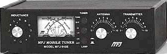
Most antenna tuners have an inductance rotary switch and two capacitors. (refer to photo at top of page) The capacitors are often labeled ANTENNA and TRANSMITTER. In some antenna tuners the inductance switch is replaced with a continuously variable inductance, popularly known as a roller inductor.
Let's assume you're using a tuner with an inductance switch, because they are the most common.SHOCK HAZARD! NEVER TRANSMIT WITH THE TUNER COVER OFF AS IN THE NEXT STEP!
TURN OFF THE POWER TO THE RADIO!
Place both capacitor controls at their mid-range positions. Don't trust the knob markers if this is your first experience with the tuner! If you are comfortable with the next procedure, remove the cover of the tuner and turn the knobs until the moving capacitor plates are only half meshed with the stationary plates. If the knobs are pointing to half scale with the reference markings on the knobs and front cover, consider yourself lucky.
If not, loosen their Allen screws and rotate the knobs so that they point to mid scale.
Re-tighten the knobs, replace the tuner cover and you're ready to go. Turn the radio on and tune receiver to an un-used frequency on the band you desire, listen for a few seconds, with the antenna and transmitter controls at mid scale, move the inductance switch to each of it's positions until you hear the loudest noise or signals coming into your radio. Then, rotate the antenna and transmitter controls until you get to the absolutely loudest noise or signal level on the radio. All three of these controls interact with each other so practice on several bands to get the "feel" of the procedure.
Select your final band of operation and repeat the procedure above. When noise peaks out using your ears and the S meter, your tuner settings should be very close for final operation.With your rig set to low power monitor the frequency to assure that it is not in use, send your ID then transmit a continuous carrier while you tweak the antenna and transmitter controls for the lowest reflected power reading with the highest output power as read on the Swr/Watt meter. You may find that you have to vary the position of the inductance switch a position or two either way to get your best match.
Play it safe and un-key before turning the inductor switch...un-key first....turn the switch...key up....repeat as needed until lowest SWR and maximum output. Be gentle to your radio; keep the key-down periods as short as possible. Depending on the impedance at the antenna input (and the overall design of the tuner) you may not be able to obtain a flat 1:1 SWR on all frequencies and bands.
Also important to remember is that your Swr will change, go up, as you tune further away from the frequency you used to "trick" your radio! So re-check and re-tune as needed as you move around the band.
You can get an idea of your SWR bandwidth by starting with your original frequency, and using the procedures above withlow power, (don't move any knobs or switches after best setting)....sweep or tune your VFO up and down the band while watching the SWR readings and note the frequency where the SWR reaches 2:1 at the higest and lowest frequency. Stop there!
Example: If your on 40 meters at say...7.262mhz as your starting point, and your SWR is 2:1 at 7.292mhz and the highest swr going the other way is 2:1 at 7.259mhz, then your "safe tuning range" without retuning the antenna tuner would be about 60khz.
Keep in mind to use very low power and ID because your signal may be heard for a split second as you tune across the band! When that transmit key is down, someone somewhere can hear you. Even a dummy load gets out somewhere!Remember your "TRICKING" your way around a good antenna!
PLEASE DISREGARD THE LINEAR AND LOW PASS FILTER FOR THE MOMENT! (Your station may not use them)
You will notice that.... first, from left to right, you have the transceiver, Swr/watt meter, ANTENNA TUNER and then the antenna on the output.
The rf moves from the transceiver to the SWR/WATT meter, then finally thru the "tuner" and out to the antenna.You just learned how to hook it all up! Just remember that our goal is to make the transceiver think all is well, and in order to "read" the SWR and Power out pertaining to "all is well"......at the radio's output....the swr meter must be between the radio and the tuner. NOT ON THE ANTENNA SIDE!Now Let's learn how to "tune" that "tuner"
Most antenna tuners have an inductance rotary switch and two capacitors. (refer to photo at top of page) The capacitors are often labeled ANTENNA and TRANSMITTER. In some antenna tuners the inductance switch is replaced with a continuously variable inductance, popularly known as a roller inductor.
Let's assume you're using a tuner with an inductance switch, because they are the most common.SHOCK HAZARD! NEVER TRANSMIT WITH THE TUNER COVER OFF AS IN THE NEXT STEP!
TURN OFF THE POWER TO THE RADIO!
Place both capacitor controls at their mid-range positions. Don't trust the knob markers if this is your first experience with the tuner! If you are comfortable with the next procedure, remove the cover of the tuner and turn the knobs until the moving capacitor plates are only half meshed with the stationary plates. If the knobs are pointing to half scale with the reference markings on the knobs and front cover, consider yourself lucky.
If not, loosen their Allen screws and rotate the knobs so that they point to mid scale.
Re-tighten the knobs, replace the tuner cover and you're ready to go. Turn the radio on and tune receiver to an un-used frequency on the band you desire, listen for a few seconds, with the antenna and transmitter controls at mid scale, move the inductance switch to each of it's positions until you hear the loudest noise or signals coming into your radio. Then, rotate the antenna and transmitter controls until you get to the absolutely loudest noise or signal level on the radio. All three of these controls interact with each other so practice on several bands to get the "feel" of the procedure.
Select your final band of operation and repeat the procedure above. When noise peaks out using your ears and the S meter, your tuner settings should be very close for final operation.With your rig set to low power monitor the frequency to assure that it is not in use, send your ID then transmit a continuous carrier while you tweak the antenna and transmitter controls for the lowest reflected power reading with the highest output power as read on the Swr/Watt meter. You may find that you have to vary the position of the inductance switch a position or two either way to get your best match.
Play it safe and un-key before turning the inductor switch...un-key first....turn the switch...key up....repeat as needed until lowest SWR and maximum output. Be gentle to your radio; keep the key-down periods as short as possible. Depending on the impedance at the antenna input (and the overall design of the tuner) you may not be able to obtain a flat 1:1 SWR on all frequencies and bands.
Also important to remember is that your Swr will change, go up, as you tune further away from the frequency you used to "trick" your radio! So re-check and re-tune as needed as you move around the band.
You can get an idea of your SWR bandwidth by starting with your original frequency, and using the procedures above withlow power, (don't move any knobs or switches after best setting)....sweep or tune your VFO up and down the band while watching the SWR readings and note the frequency where the SWR reaches 2:1 at the higest and lowest frequency. Stop there!
Example: If your on 40 meters at say...7.262mhz as your starting point, and your SWR is 2:1 at 7.292mhz and the highest swr going the other way is 2:1 at 7.259mhz, then your "safe tuning range" without retuning the antenna tuner would be about 60khz.
Keep in mind to use very low power and ID because your signal may be heard for a split second as you tune across the band! When that transmit key is down, someone somewhere can hear you. Even a dummy load gets out somewhere!Remember your "TRICKING" your way around a good antenna!
6 Tip Motivasi
 Tulisan ini saya tujukan untuk memotivasi diri saya sendiri. Semoga dapat memberi manfaat kepada sahabat yang telah secara rutin dan berkala berkunjung ke halaman-halaman pada web ini ataupun yang kebetulan mampir.
6 Tips motivasi
Secara ringkas, motivasi adalah semangat pendorong untuk melakukan sesuatu. Berikut ini adalah beberapa tips motivasi yang semoga bermanfaat.
1. Selalu bersyukur akan apa yang kita dapatkan.
Mungkin hal ini adalah sederhana, namun sangat memotivasi diri kita saat kita terpukul atau terjatuh dengan target-target yang dinanti-nanti dan diharapkan untuk terjadi, tapi faktanya meleset. Pengungkapan syukur melalui 3 cara.
- Dengan hati. Lihatlah sekeliling kita yang ada dibawah kita. Yakin hal ini akan membuat hati kita lembut dan mensyukuri akan nikmat-nikmat yang oleh sebagian orang tidak dapat menikmatinya.
- Dengan lisan, dengan ucapkan alhamdulillah. Nikmat yang kita rasakan tidak akan kita peroleh tanpa seijin dari pemilik tubuh kita, pemilik jasad kita, juga pemilik ruh kita. Trus kita ini siapa? Kita adalah makhluk yang diberi pinjaman untuk dapat berkarya, dan membagikan kebahagiaan kepada orang lain.
- Dengan perbuatan. Syukur dengan membagikan kebahagiaan kepada orang lain. Rasakanlah kebahagiaan yang timbul saat kita dapat melihat kebahagiaan yang muncul melalui tangan kita. Ada rasa menyeruak dalam dada merasakan bahagia meski buliran air mata mengalir tidak terasa. Jika kita pernah merasakannya, ulangi ulangi dan ulangi.
Hal ini akan memotivasi kita untuk melakukannya. Karena dengannya kita merasa enjoy, dan dengannya tak kan ada rasa bosan dan letih. Banyak dari saudara kita yang mereka bekerja karena tuntutan, bukan karena mereka menyukainya. Dari hasilnya kita akan tahu mana yang bekerja karena menyukainya, atau bekerja karena tuntutan. Orang bekerja dengan diikuti rasa senang, akan menambahkan detil-detil secara sukarela.
3. Jika tidak seperti yang kita inginkan.
Yakinkan pada diri sendiri, jika posisi ini adalah step awal menuju yang kita inginkan. Tentunya ada hikmahnya. Apapun keadaanannya. Tetap lakukan yang terbaik yang kita bisa, karena itu memperlihatkan kualitas kita.
4. Cermati, perhitungkan, dan tangkap peluang yang ada.
Setiap kita memiliki peluang-peluang menuju sukses. Namun hanya sedikit orang yang mampu memanfaatkan peluang itu. Terkadang kita melihat ada peluang, namun memiliki keterbatasan, misal keterbatasan modal, keterbatasan keahlian dan lain-lain. Itulah gunanya bermasyarakat, adanya berinteraksi, bersosialisasi, dan bertolong-menolong. Dengan bekerja sama tentu akan menghasilkan yang positif sesuai target dan keinginan bersama. Asah terus kemampuan untuk melihat peluang.
5. Berkumpul dengan orang yang bermotivasi.
Prinsip ini sama dengan istilah penjual minyak wangi akan berbau wangi dengan sendirinya.
6. Selalu dekatkan diri pada Allah.
Adakalanya dalam berusaha mengalami pasang surut. Hambatan dan rintangan dalam melangkah. Pastikan pada diri sendiri bahwa semua itu ada hikmahnya. Mungkin sajakan itu adalah cara Allah untuk mendidik kita. Kita tidak akan dididik seperti di bangku sekolah, tapi kita dididik melalui peristiwa-peristiwa. Kita akan mendapatkan pelajaran dari universitas yang skalanya lebih besar. yaitu universitas kehidupan.
Semoga kita termasuk orang-orang yang dapat memberi manfaat kepada orang lain. Semoga Allah mengijinkannya.. Amin..
Tidaklah sesuatu berubah jika tidak mulai bertindak, dan kapankah waktu yang paling sesuai untuk memulainya jika bukan saat ini.
Esensi Kehidupan Adalah Memberi
 Jika kita tau siapa diri kita,darimana berasal,untuk apa hidup didunia,setelah itu mau kemana lagi melangkah/melanjutkan hidup,rasanya jika tiap diri ini sadar akan semua hal itu tak akan banyak kita temui keluh kesah dalam menjalani kehidupan ini.
Kehidupan ini sendiri adalah pemberian dari Sang Maha Pemberi. Saat kita dilahirkan ke dunia ini, kita pun mendapat pemberian kasih sayang dari orang tua. Bayangkan jika kita lahir tanpa ada orang yang memberi kasih sayang itu, niscaya kita tak kan ada sampai saat ini. Semua hal yang kita manfaatkan dalam hidup ini adalah pemberian(taken for granted). Apa yang diberikan itu tanpa pamrih. Tanpa mengharap balasan.
Saat ini kita telah dewasa, atau lebih dari kata dewasa itu sendiri. Sudah saatnya untuk tidak hanya menerima, tapi memberi. Memberi apa yang kita punya dan kita sanggup untuk memberikannya. Tidak perlu muluk-muluk, hal-hal yang sederhana saja. Memberikan senyuman ke orang yang berpapasan dengan kita, memberikan kasih sayang dan perhatian ke orang tua kita. Membuatkan minuman mungkin, memberikan salam saat pergi ataupun pulang, atau juga memberikan ciuman di tangan beliau.
Adanya kehidupan kita saat ini tidaklah secara tiba-tiba, dan tidaklah dengan sendirinya tanpa ada tanpa campur tangan orang lain. Orang-orang disekeliling kita sangat berperan akan keberadaan kita. Tapi mengapa banyak yang tidak menyadarinya? Oleh karenanya, saatnya untuk memberi.
Banyak hal yang ingin kita capai,seperti pekerjaan,cita-cita,jodoh kita dan lain sebagainya,sebelum kita dapatkan harus ada perjuangan, yakni tenaga ,pikiran dan waktu. Ada pepatah berilah, maka kau akan menerima lebih. Hal ini bukan berarti apa yang dilakukan adalah berpamrih, mengharapkan imbalan. Memberi merupakan tolak ukur kesadaran dan keikhlasan. Jika memberi dengan diiringi keinginan untuk suatu balasan, dan penerima pun mengabulkannya, maka itu bukanlah pemberian yang utuh. Namun sebuah negosiasi. Negosiasi berkutat antara untung dan rugi. Bukan lagi mendasarkan pada hati nurani.
Setiap pemberian pasti ada balasannya, akan dilipat gandakan. Jika anda tidak percaya, cobalah dan lakukanlah. Lihat dan hitunglah dengan objektif. Balasan itu tidak hanya berupa nominal angka mata uang, tidak juga barang, namun juga bisa berupa hadirnya kesempatan, terjaganya kesehatan, bertambahnya ilmu pengetahuan dan masih banyak lagi manfaat yang didapatkan. Belum lagi bertambahnya pahala.
Jika tiap orang sadar dan faham arti memberi ini,mungkin tidak akan kita temukan istilah pelit, sengsara atau miskin. tiap orang yang sadar hidupnya adalah pemberian akan memberikan lagi kepada orang lain baik itu moril atau materil. Kembali kepadanya dalam bentuk lain, sehingga seperti sebuah siklus..
Langganan:
Postingan (Atom)